Moog was recently tasked, as part of a research project for its Naval Business Unit, to fit fifteen times the amount of power without increasing volume into a peak sine drive controller. By refining topologies, designs, and mixing it with fluid coolant, Moog met the challenge.

The test unit that was developed to understand the effects of the dielectric fluid.
For some time, Moog has designed – at low structure borne vibration noise level – 10 kilowatt peak sine drive controllers. To build on that, Moog set out to develop a 150 kW peak controller. This following investigation examined the challenges of increasing the power of that drive topology.
Four areas predominately impact power density: reducing losses, high thermal conductivity, increased operating temperature and reduced package volume. This research study encompassed these aspects.
To reduce the losses within the controller, company engineers performed a trade study using Silicone Carbide (SiC) switching devices in a multilevel configuration. SiC MOSFETs have proven to have lower conduction losses, lower switching losses, and operate at higher temperatures when compared to Silicon MOSFETs and Insulated Gate Bipolar Transistors. Moog engineers increased output voltage to about double that of the baseline design to help decrease the output current and reduce filter losses. Therefore, a multilevel configuration versus a standard inverter would provide for a reduction in voltage stress on the desired switching devices. The overall controller was designed for a system efficiency of 95%.
Although the Moog team was able to increase efficiency, they still had to manage 7.5 kW of heat. Various cooling and heat management methods were investigated including natural convection, forced air, liquid cooling, and heat pipes. The engineers considered factors such as weight, heat transfer, conductivity, complexity, cost and feasibility. The methods providing most cooling benefit were water cooling for managing external heat and dielectric fluid to handle the internal heat.

A resistor boils in the Novec fluid
For a better understanding of the dielectric fluid immersion along with the SiC devices, Moog engineers developed a test unit that could house high-power resistors, inductors, and the SiC devices along with its drive circuitry. The engineered dielectric fluid selected has a slightly higher conductivity than air, but the main heat-transfer method of the fluid is phase changing, boiling from a liquid into a vapor. When a liquid boils it takes energy, the heat of vaporization, to change from a liquid to a gas. During this phase change, the temperature of the liquid remains constant. Condensing is the second part of the two-phase cycle. All heat absorbed by the vapor rises with the vapor and must be transferred to the condenser for the phase change from vapor back to liquid. The liquid cold plate removes heat from the enclosure to an external heat exchanger.
For a test, Moog engineers placed power resistors at various orientations to understand different boiling affects. The resistors used for testing are rated for 260W in a typical air cooled, heat-sink mounted arrangement wherein the dielectric fluid provides power levels close to four times the rated power of the devices without destroying the device.

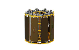
The illustration compares the large 10-kW controller enclosure with the new and smaller 150-kW unit.
The SiC module circuit card along with the module was submerged in the Novec fluid, but because it has a dielectric constant nine times that of air, Moog engineers believe surface currents hindered the system from running for long periods. They developed an inductor for the overall 150-kW design and tested that in the fluid as well, but were unable to obtain boiling at 200A which was the limit of the supply. To further investigate the size reduction of the inductor, they took a copper strip, 4.5 x 0.5 x 0.0014-in., and performed the same test. This small piece of copper, which would have vaporized in air well below the 200A level, was boiling the Novec fluid and remaining at a stable temperature of 55°C. This information led to a reduction in size of the inductors and overall filter size.
With the information from testing, compared to the 10 kW design, Moog engineers developed a controller capable of handling 15 times the power and occupying a smaller volume for or a 30-fold increase in power density over the conventional design. Although the engineers report tremendous benefit in submerging inductors in fluid, another benefit arose: the dielectric fluid helped eliminate extreme explosive arcs. The fuse industry could also benefit using Novec fluid. 
Moog
Filed Under: News


Great article!